You have no items in your shopping cart.
Spanning Tree Protocol Mistakes and How to Avoid Them
In this guide, we will explore essential Spanning Tree Protocol Configuration strategies and Network Best Practices to help you avoid common pitfalls in managing your network topology.
The Spanning Tree Protocol (STP) is essential in Ethernet networks to prevent loops. It involves a series of processes and states, such as the blocking state and forwarding state, to manage switch ports and ensure efficient data flow.
Before we jump into the mistakes, let’s delve deeper into how STP functions, laying the groundwork for understanding the common mistakes that follow.
Let’s start by understanding how STP works so we can eliminate the possible issues caused by STP. The Spanning Tree Protocol (STP) protects networks from loops and instability. Nevertheless, even the most experienced network administrators might need help with frequent mistakes. This article delves into the subtleties of STP and highlights several common faults that can disrupt a network's delicate equilibrium.
The Role of STP in Preventing Network Loops
The Spanning Tree Protocol (STP) (IEEE 802.1D) is mainly employed to avoid layer two loops and broadcast storms while also serving the purpose of network redundancy. Initially, it was designed in an era when tolerating recovery times of a minute or more after an outage was deemed acceptable.
However, with technological advancements and the increasing dependence of critical applications on stable connections, businesses have shifted away from these extended recovery times, seeking faster and more efficient solutions over the years.
Guiding Principles to Avoid STP Misconfigurations
· Every switch in a network must choose a root switch, and only the functioning interfaces on the root switch/bridge are set to forwarding mode.
· The other switches in the network, known as non-root switches/bridges, determine the best path to the root switch.
· The port that connects to the root switch (root port) is configured to route traffic. On shared Ethernet segments, the switch with the optimal path to the root switch is put into forwarding mode. This switch is called the designated switch, and its port is referred to as the designated port.
· All other interfaces are set to blocking mode and will not forward frames.
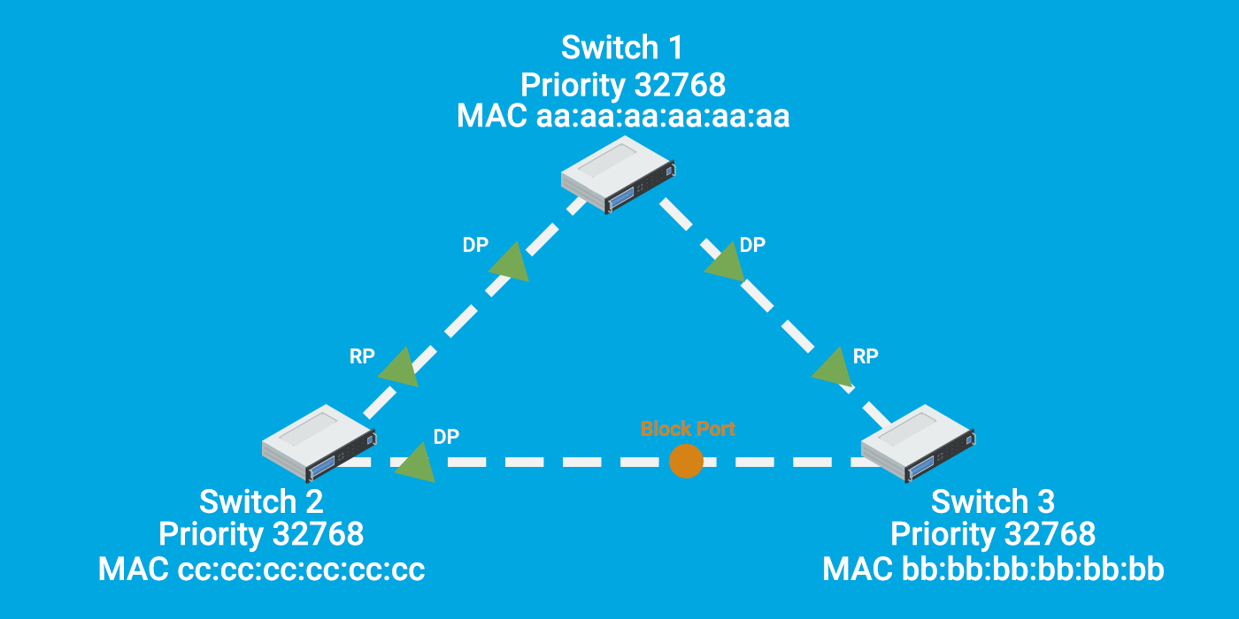
As you can see in the image below, the CLI command indicates that the orange port is currently in a blocked state on Switch 3, and Switch 1 is the ROOT bridge, also referred to as the root switch. Most of the time, STP is enabled by default on all switches. (Please note that the command can vary based on the switch you use.)
Let's talk about mistakes you can avoid while working on STP.
1. Avoid Automatic Root Switch Assignment
When we have switches in our data center and plan to add more later, it is crucial to closely check the Spanning Tree Protocol (STP) configuration before the new switch automatically becomes the root bridge or creates a loop in the network. Therefore, carefully checking the redundancy links is the primary key to avoiding issues with the root bridge.
Allowing a switch to become the root switch involves configuring the switch with appropriate parameters to participate in the Spanning Tree Protocol (STP) election process.
Here are the key steps to let a button decide to become the root switch:
· Default Configuration:
You may control the Root Bridge Election by changing the Bridge Priority on your switches. The default value is 32768, and the lower number is preferable. In the event of a tie, the switch with the lowest MAC address will be used.
· Check Current Bridge Priority:
It's important to check the current Bridge Priority of the switch. If you want the switch to have a higher priority (lower numerical value) than the existing root bridge, you may need to adjust its Bridge Priority.
· Lower Bridge Priority:
To increase the chances of the switch becoming the root bridge, lower its Bridge Priority. The Bridge Priority is a 2-byte value, and it is typically configured in increments of 4096. The default priority is 32768, so lowering it to a value less than the existing root bridge's priority will make this switch more likely to be elected as the root.
Different interface types, including Ethernet (10 Mbit), FastEthernet (100Mbit), and Gigabit (1000Mbit), are visible. The top switch, SW1 in image1, serves as the root bridge, making all other switches non-root and requiring them to determine the shortest path to the root bridge.
You can change the Lower Bridge Priority as shown in the image below.
Cisco CLI Command: spanning-tree vlan <VLAN_ID> priority <NEW_PRIORITY>
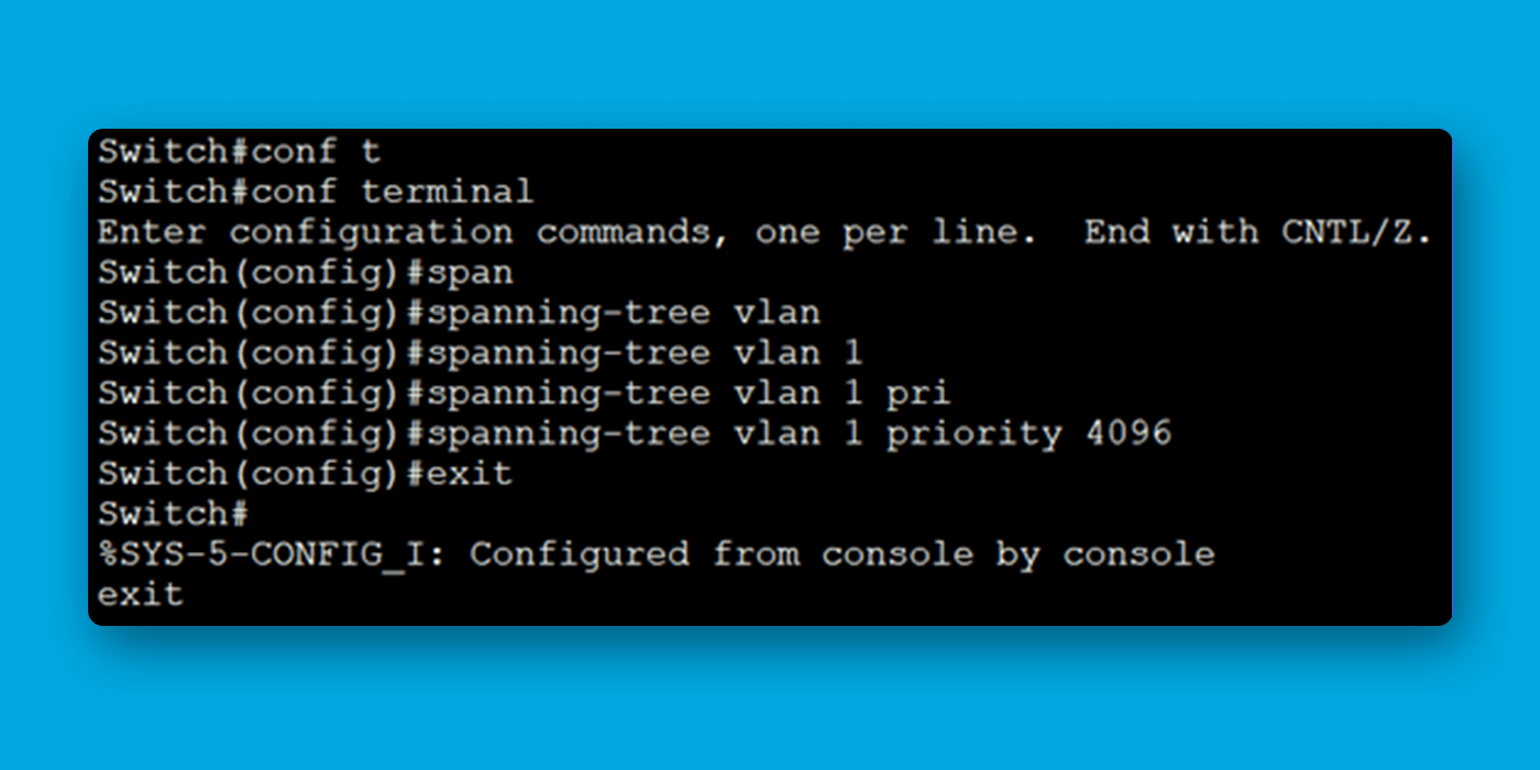
Cisco CLI Command: Replace <VLAN_ID> with the VLAN ID you want to configure, and <NEW_PRIORITY> with the desired priority value to make the switch as Root Bridge
Verify Configuration:
After configuring the lower new Bridge Priority switch will become the root bridge, and in the event of a tie, the switch with the lowest MAC address will be used Since MAC addresses are chosen by the switch manufacturer, addresses are usually assigned sequentially. That means that new switches have higher MAC addresses than old ones. If STP used the highest bridge ID, then whenever a new switch (or a replacement switch) would be added to the network, the root would change (since the new switch has a higher MAC address). This would cause interruptions and unexpected topology changes.
show spanning-tree command: - Look for the "Root ID" information to confirm that the switch now has a lower priority and root bridge has the same MAC address in ROOD ID and Bridge ID.
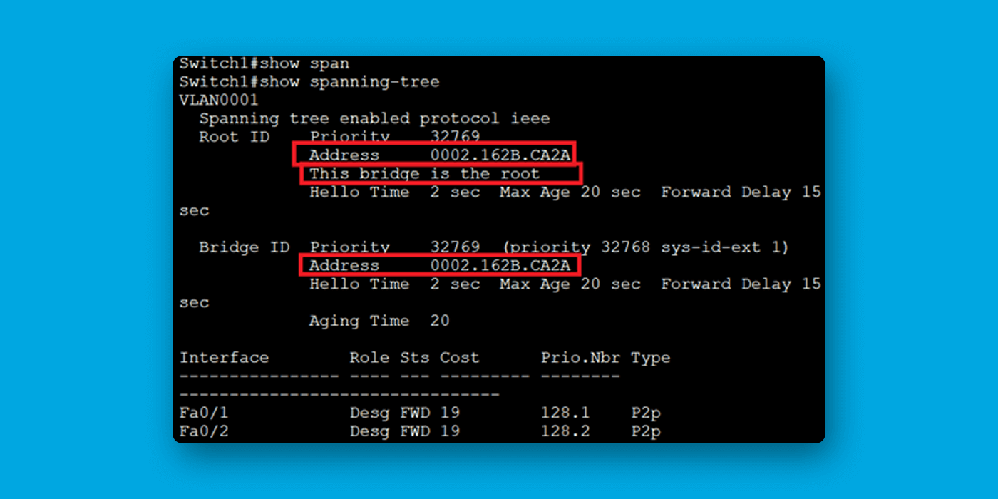
Best Practices for Root Bridge Election
· Monitoring STP Elections:
STP convergence may take some time, and the switch will actively participate in the election process. Observe the STP election results to confirm if the switch becomes the root bridge.
· Continuous Review and Adjustment:
Periodically review the STP status and adjust configurations as needed. It's crucial to ensure that the network topology remains stable and the switch continues to act as the root bridge if that is the desired outcome.
We recommend not letting the switch decide the Root bridge. Please configure it manually when setting up your network infrastructure.
Optimizing Spanning-Tree Path Costs
By understanding cost calculation, you can effectively manage STP for loop prevention and optimal network performance.
Understanding IEEE 802.1D Path Cost Metrics
|
|||
|
Link Speed |
Recommended |
Recommended |
Range |
|
Value |
Range |
||
|
4 Mbps |
250 |
100-1000 |
1-65535 |
|
10 Mbps |
100 |
50-600 |
1-65535 |
|
16 Mbps |
62 |
40-400 |
1-65535 |
|
100 Mbps |
19 |
Oct-60 |
1-65535 |
|
1 Gbps |
4 |
10-Mar |
1-65535 |
|
10 Gbps |
2 |
5-Jan |
1-65535 |
Default Observed on Cisco Switches
|
|||
|
Speed |
Port Cost |
Comment |
|
|
10 Mbps |
100 |
Ethernet |
|
|
20 Mbps |
56 |
EtherChannel |
|
|
30 Mbps |
47 |
EtherChannel |
|
|
40 Mbps |
41 |
EtherChannel |
|
|
50 Mbps |
35 |
EtherChannel |
|
|
54 Mbps |
33 |
802.11 wireless |
|
|
60 Mbps |
30 |
EtherChannel |
|
|
70 Mbps |
26 |
EtherChannel |
|
|
80 Mbps |
23 |
EtherChannel |
|
|
100 Mbps |
19 |
Fast Ethernet |
|
|
200 Mbps |
12 |
Fast EtherChannel |
|
|
300 Mbps |
9 |
Fast EtherChannel |
|
|
400 Mbps |
8 |
Fast EtherChannel |
|
|
500 Mbps |
7 |
Fast EtherChannel |
|
|
600 Mbps |
6 |
Fast EtherChannel |
|
|
700 Mbps |
5 |
Fast EtherChannel |
|
|
800 Mbps |
5 |
Fast EtherChannel |
|
|
1 Gbps |
4 |
Gigabit Ethernet |
|
|
2 Gbps |
3 |
Gigabit EtherChannel |
|
|
10 Gbps |
2 |
10G Ethernet |
|
|
20 Gbps |
1 |
20G EtherChannel |
|
|
40 Gbps |
1 |
40G EtherChannel |
|
2. The Importance of Adhering to the 802.1D Standard
The 802.1D standard defines the original Spanning Tree Protocol (STP), which prevents loops in Ethernet networks by creating a loop-free logical topology. However, 802.1D has some limitations, including slow convergence times. Various advanced versions and enhancements to the original Spanning Tree Protocol have been developed to address these limitations.
One such advanced version is the Rapid Spanning Tree Protocol (RSTP), defined in the 802.1w standard. RSTP provides faster convergence times compared to the original STP. It achieves this by using faster mechanisms for detecting topology changes and recalculating the spanning tree.
STP Convergence Time:
STP, as defined in the 802.1D standard, has a relatively slow convergence time.
After a topology change (e.g., link failure or recovery), STP typically takes about 30 seconds or more to converge. This slow convergence time can result in noticeable delays in adapting to network changes.
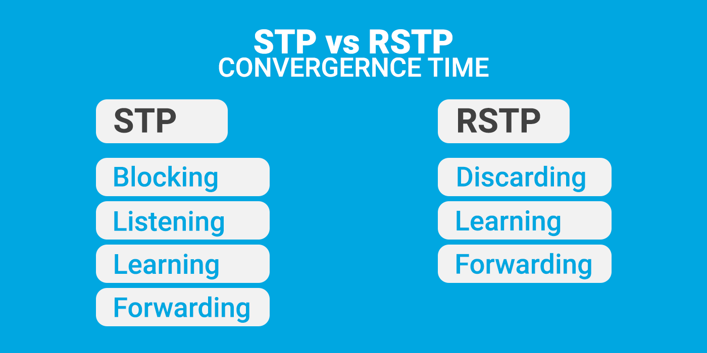
RSTP Convergence Time:
RSTP is designed to provide rapid convergence and improve upon the slow convergence of STP.
RSTP achieves faster convergence through mechanisms such as the Topology Change Notification (TCN) mechanism, proposal/agreement process, alternate port roles, and edge port features.
RSTP can typically converge within the range of 1 to 3 seconds after a topology change, making it much quicker than STP.
3. Not selecting the right switch for the root bridge
We need to select the correct switch for the Root bridge to avoid any issues or slowness in the network later. Choosing the wrong switch, which can only handle a limited amount of traffic, may hamper your network's performance. Therefore, before electing the root bridge, check your topology and review all your switch configurations and CPU utilization. Designate the core switch as the root bridge because it can handle much traffic, and your network traffic will flow through the core switch. However, verify the hop count; it should be lower if you make the core switch the root bridge. In many topologies, the "core" is the central node in a hierarchical topology. As such, it's often the "best" root bridge. Root switch placement is optimally determined by trying to achieve the shortest number of hops for most of your traffic.
This is a really bad example. As you can see, an L2 switch with fewer capabilities wins the STP election and becomes the root bridge, so we don't want this to happen.
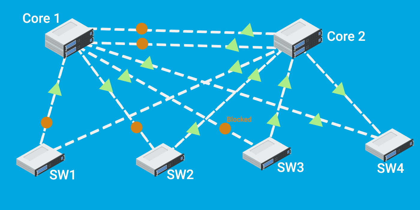
When you have multiple VLANs, questions might be coming to your mind. Do all frames go through the root bridge within the different VLANs?
No, frames from different VLANs can take different paths in a network, and they may not necessarily all pass through the root bridge. Each VLAN has its own spanning-tree instance, and the spanning tree algorithm works independently for each VLAN where the Per VLAN Spanning Tree (PVST) comes into the picture.
In a network with multiple VLANs, there can be different root bridges for different VLANs, depending on the spanning tree topology and the configuration of each VLAN. The paths taken by frames within one VLAN are determined by the spanning tree algorithm for that specific VLAN, and these paths may not coincide with those of frames from other VLANs.
So, frames from different VLANs might go through different switches, and the paths they take are determined by the spanning tree topology within each VLAN, potentially resulting in different switches acting as root bridges for different VLANs.
4. Addressing the Dilemma of Inconsistent Path Costs
Inconsistent path costs occur when different cost values are assigned to links for the same distance. For example, if two switches have different cost values for a link with the same speed, the results can be inconsistent. By addressing inconsistent path costs, network administrators can maintain a stable and loop-free network environment, allowing STP to function optimally and select the best paths based on accurate cost calculations.
· The Consequences of Loops:
If switches calculate different paths due to inconsistent costs, it can create loops in the network, causing traffic to be lost or sent in endless circles.
· The Impact of Slow Convergence:
When topology changes (e.g., link failure), switches need to recalculate the spanning tree. Inconsistent costs can slow down this process, leading to temporary connectivity issues.
· Navigating Suboptimal Performance Issues:
If the chosen paths are not actually the best due to inaccurate cost calculations, it can cause bottlenecks and affect overall network performance.
Ensure that all switches in your network are using the same version of STP. Inconsistent STP versions can lead to variations in how path costs are calculated, causing inconsistencies.
5. The Risks of Unmanaged Redundant Links
Using redundant links between switches without enabling Spanning Tree Protocol (STP) is a common mistake that can result in network loops and performance concerns. Here's why this is a problem and how you can fix it:
· Without STP, redundant links between switches can create loops in the network.
· When loops occur, broadcast storms may arise, causing network congestion and degradation of performance.
· Network devices might experience higher CPU utilization due to the excessive broadcast traffic caused by loops.
6. The Drawbacks of Disabling STP
Disabling STP or relying solely on link aggregation protocols (LACP) for loop prevention can create unexpected loops and network instability.
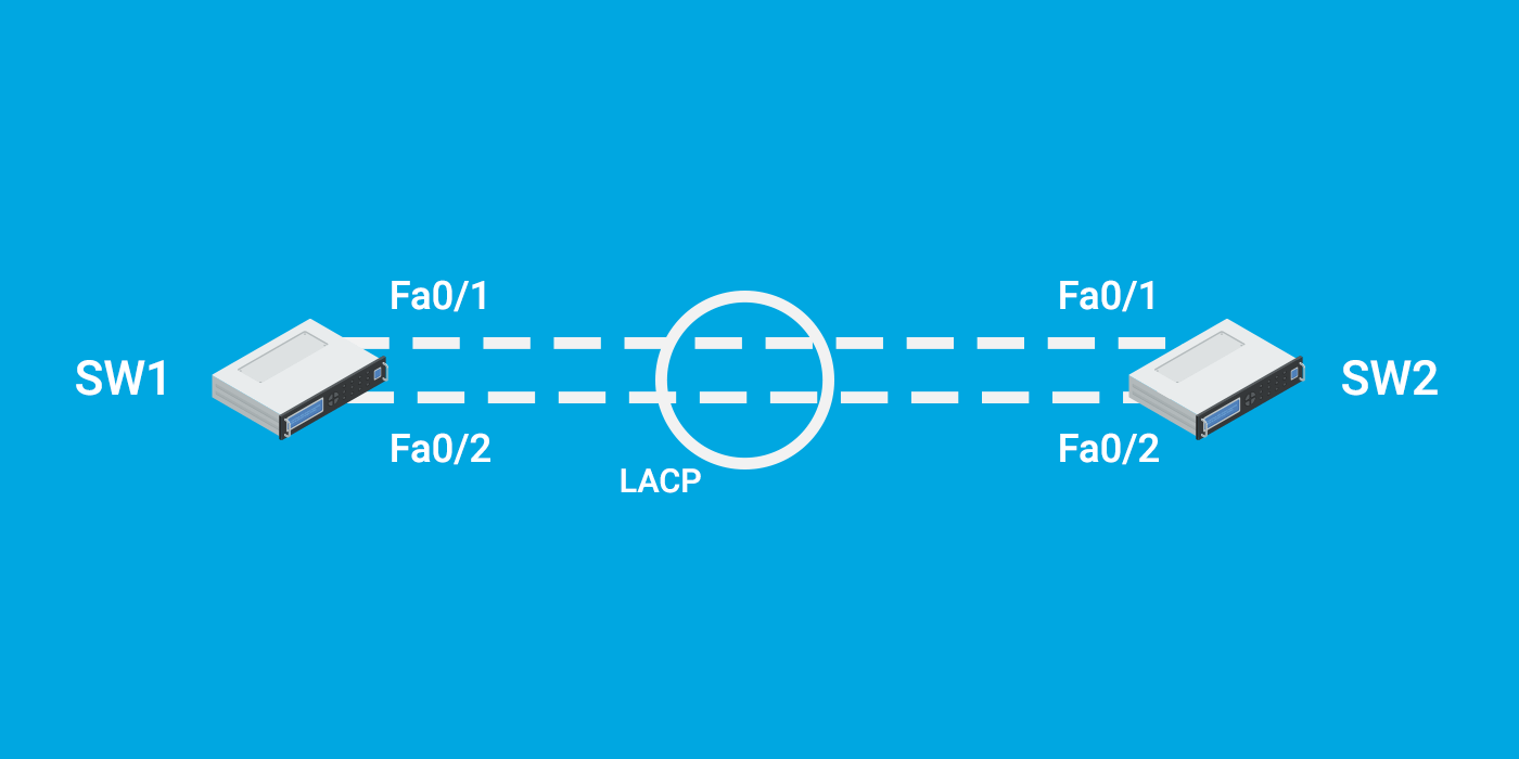
Link aggregation protocols like LACP are used to bundle multiple physical links into a single logical link to increase bandwidth and provide redundancy. While LACP doesn't prevent loops, it works best when used with STP. STP ensures that only one path is active at a time to avoid loops, and LACP helps distribute traffic across the available links.
In summary, having a proper combination of STP and link aggregation protocols is crucial to ensure network stability, prevent loops, and maintain efficient traffic distribution. Disabling STP or relying solely on LACP without considering loop prevention mechanisms can lead to unpredictable and undesirable network behavior.
Conclusion
In conclusion, ensuring network stability heavily relies on the effective implementation of the Spanning Tree Protocol (STP) and preventing loops. However, misconfigurations and a lack of understanding can lead to significant problems. You can configure and manage STP effectively for a healthy and resilient network by being aware of common STP mistakes and following best practices.


