
Palo Alto Networks firewalls are industry-leading next-generation firewalls (NGFWs) designed to provide network security, threat prevention, and application-aware filtering in enterprise and small business environments.
Configuring a Palo Alto Firewall can feel like navigating uncharted waters. As Grace Hopper once said, “A ship in port is safe, but that’s not what ships are built for.” In the same spirit, your network is meant to be secure yet agile, ready for both routine traffic and unexpected challenges.
In this guide, you’ll learn how to perform a basic configuration on a Palo Alto Firewall using a lab setup—covering everything from initial interface configuration to setting up NAT. Whether you’re a seasoned network engineer or a newcomer to next-generation firewalls, these steps will help you establish a strong security baseline.
Step 1: Understanding the Management (MGMT) Interface
The initial configuration of a Palo Alto Firewall can be done either through the dedicated management interface or via a console connection. By default, the firewall comes pre-configured with a management interface set to the IP address 192.168.1.1/24. The default login credentials are admin for both the username and password.
Once you connect to the management interface, you can configure a Palo Alto firewall using the CLI or the GUI. While I prefer using the CLI for basic configurations, you have the choice. I will demonstrate both methods.
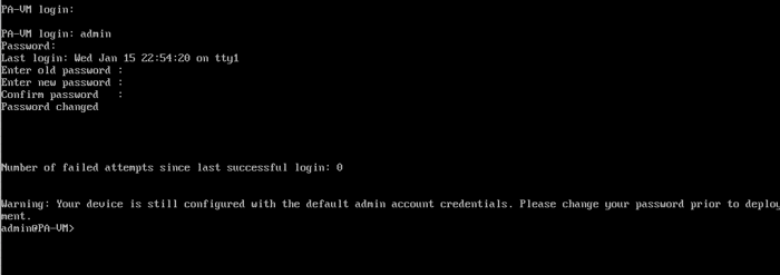
Log in with the default username and password, admin. You will be prompted to change the default password. Enter the old password, then the new one, and confirm the new one.
In Palo Alto Firewalls, the ">" and "#" symbols represent different command-line modes:
1. ">" (greater than symbol) indicates that you are in user mode or operational mode. In this mode, you can run commands to view the firewall’s status, configuration, and logs, but you cannot modify the configuration directly.
2. "#" (hash symbol) indicates that you are in configuration mode. In this mode, you can modify the firewall’s configuration, including changes to network settings, policies, and system configurations.
To switch between these modes:
- From user mode (">"), use the command configure command to enter configuration mode.
- From configuration mode ("#"), use the command exit command to return to user mode or run before your command.
1.1. Configuring the MGMT Interface CLI:
admin@PA-VM> configure
admin@PA-VM# set deviceconfig system ip-address 192.168.24.251 netmask 255.255.255.0 default-gateway 192.168.24.24
admin@PA-VM# commit
admin@PA-VM# run show interface management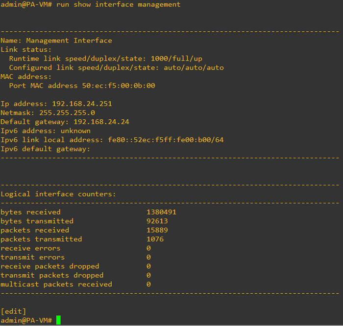
You can set up additional parameters for the management interface using the following commands:
#set deviceconfig system type [static | dhcp-client]
#set deviceconfig system ip-address <ip address>
#set deviceconfig system netmask <netmask>
#set deviceconfig system default-gateway <default gateway>
#set deviceconfig system dns-setting servers primary <DNS ip address>
#set deviceconfig system dns-setting servers secondary <DNS ip address>
#set deviceconfig system timezone
#set deviceconfig system hostname <hostname>
#set deviceconfig system domain   <domain name>
#set deviceconfig system login-banner ‘your_text’
After completing your configuration, whether through the CLI or GUI, it is essential to commit your changes.
Why is this necessary? Configuration changes are initially staged and not active when using Palo Alto Networks firewalls until you commit them. Committing your configuration applies your modifications and ensures they remain effective after rebooting. This step is crucial for activating and enforcing the new system settings.
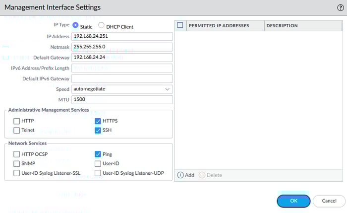
1.2. Configuring the MGMT Interface via GUI:
You can configure the management interface using the web GUI. First, assign an IP address to your computer's Ethernet interface within the 192.168.1.0/24 range and connect it to the MGMT interface with an Ethernet cable.
Open a web browser and navigate to https://192.168.1.1 to access the login page. Use the default username and password to log in (admin, admin). Once logged in, go to Device > Setup > Management and select the management interface. Here, you can configure all parameters that can also be set via the CLI.
Step 2: Creating Security Zones for Network Segmentation
Security zones help enforce Zero Trust Network Architecture principles by separating traffic into trusted and untrusted domains.
2.1. Configure Security Zones
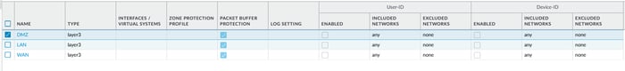
In this step, we need to create zones. Our diagram shows three zones: WAN, LAN, and DMZ. 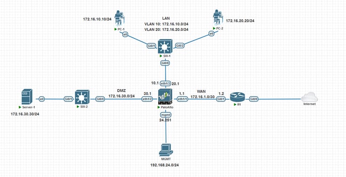
Select the Network tab from the top-level tabs, select zones, and click the Add buttons. Network > Zones > add 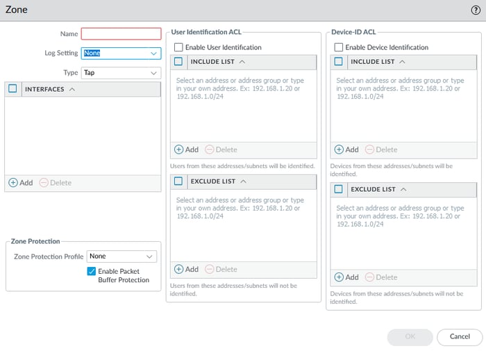
It would be more effective to demonstrate again some concepts in this area.
Type: In Palo Alto Firewalls, the Zone Types define the type of traffic a zone can handle and how it interacts with other zones. The most common zone types are:
- Layer 3 (L3) Zone: This zone is used for routing interfaces. It is typically used for networks where routing occurs, such as internal, external, or DMZ networks.
- Layer 2 (L2) Zone: This zone is used for switch interfaces. Traffic within this zone is bridged (not routed), meaning devices in the same zone can communicate without routing.
These zone types define how the traffic is handled and whether the firewall performs routing, bridging, or allows traffic through transparently. Please check part two of the Palo Alto Firewall Setup for additional details.
- Zone Protection: Zone protection is a security feature designed to protect specific areas within a network or system from various types of attacks, including floods, packet-based threats, and non-IP protocol-based attacks.
- This feature typically involves defining protection profiles that manage and filter traffic, preventing unauthorized or harmful traffic from entering the network through firewall interfaces.
- Enable Packet Buffer Protection (PBP) is a feature designed to safeguard firewall resources from malicious traffic, ensuring that such traffic does not overwhelm and potentially disrupt the firewall's functionality.
- By implementing PBP, networks can defend against threats such as Denial of Service (DoS) attacks, enhancing the overall security and stability of the network infrastructure.
Interfaces: Add one or more interfaces to this zone.
In the picture below, three zones were created, and layer three was selected as the interface type without setting any other parameters.
Step 3: Configuring Layer 3 Interfaces
Interfaces in Palo Alto firewalls are physical or virtual network connections that allow communication between different network segments. Depending on the desired functionality and network design, they can be configured in various modes, such as Layer 3, Layer 2, or virtual wire.
3.1 Configure Interfaces
This is My IP Plan:
Interfaces     IP Address
Ethernet1/1  172.16.1.1/30
Ethernet1/2 172.16.30.1/24
Ethernet1/3 172.16.10.0/24, 172.16.20.0/24
Before configuring IP addresses for Interfaces, we need to create Management Profiles.
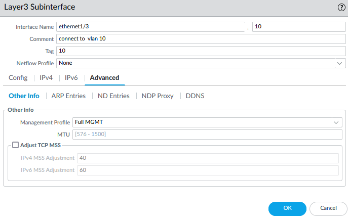
A management profile in Palo Alto firewalls defines the access permissions and protocols used to manage the device, such as HTTP, HTTPS, SSH, or SNMP. It is assigned to interfaces to control which management services are available and secure on specific network interfaces.
A management profile can help troubleshoot by allowing access to the firewall's management functions for diagnostics and configuration.
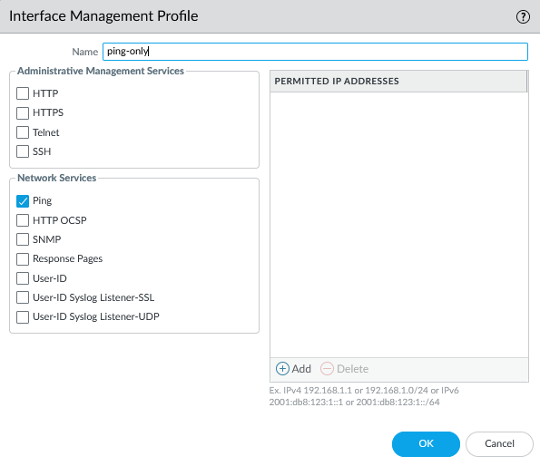
To create a Management Profile, navigate to Network > Network Profiles > Interface Management. I have created two profiles: one set to PING only and another to PING, HTTPS, SSH, and SNMP.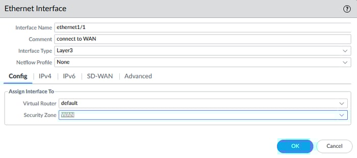
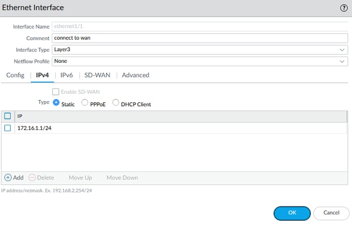
Now, we can configure the interfaces.
Navigate to Network > Interfaces > and double-click the desired interface to configure it.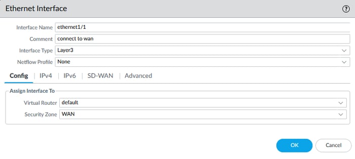
During configuration, you might ask, "What is a virtual router?" I will discuss it in the next step, but select the virtual router values as the default for now.
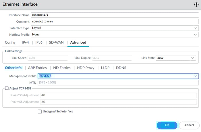
In the Advanced tab, I selected the ping-only profile for the management profile settings.
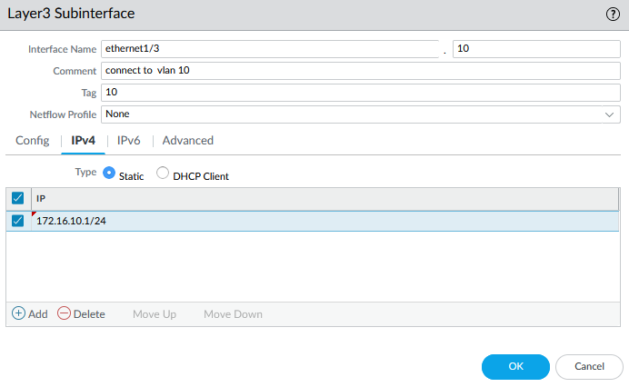
3.2 Configure SUB Interface
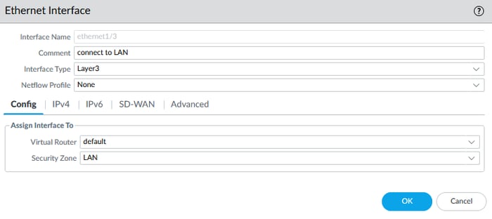
According to our diagram, Interface Ethernet1/3 has two sub-interfaces. To configure a sub-interface, you first need to configure the Physical Interface and then add the sub-interface to the physical interface.
When configuring the physical interface for a sub-interface, you do not need to enter an IPv4 address. However, you should enter an IPv4 address for each sub-interface. In the picture below, I configured the physical interface in the first step.
After configuring the physical interface, please select it and click the Add Subinterface icon.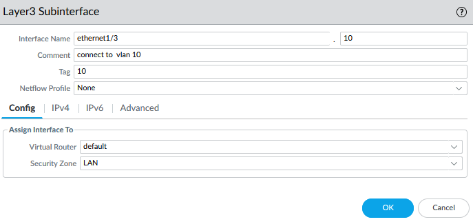
In front of the interface name, a dot, and a box display the value of ten. Let me give you a hint: I think you know the concept of Router-On-A-Stick. The value of ten refers to the virtual interface name; you can select any number.
Still, for clear and straightforward configuration, following a consistent and logical naming convention that matches the VLAN ID with the interface identifier is generally a good practice.
Step 4: Virtual Router
Virtual Routers in Palo Alto firewalls are logical routing entities that manage Layer 3 traffic by maintaining and applying routing tables for connected networks.
- Each virtual router operates independently, allowing multiple routing instances on the same firewall to segregate traffic for different networks or tenants.
- Palo Alto firewalls come with a default virtual router, which can be used for basic routing needs or customized for specific network requirements.
- Virtual routers support static, dynamic (OSPF, BGP, RIP), and policy-based routing to ensure flexible and efficient traffic management across diverse network architectures.
4.1 Configure Virtual Router
Navigate to the Network section and select Virtual Router. You will see that all the interfaces configured in the previous steps have been added to the default virtual router that was created by default.
When all interfaces are placed in the same virtual router on a Palo Alto firewall, they share the same routing table, enabling seamless communication without requiring additional routing configurations.
This approach simplifies the setup and enhances efficiency, making it ideal for smaller, less complex networks. It also allows for a unified routing policy, streamlining management and improving overall performance.
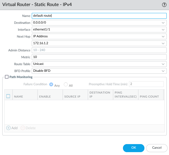
You can create a static route in the default virtual router. According to our diagram, we must create a default route toward R1.
Step 5: Building a Network Security Baseline with Security Policies
Palo Alto Firewalls enforce security policies to allow or deny access. They do this by enforcing rules in a top-down, left-to-right sequence. If no user-defined rule matches, default rules at the bottom of the rule base apply. Policies can range from simple (source/destination zones) to advanced (addresses, ports, applications, and URL categories).
Three types of rules exist:
- Intra-zone: Allows traffic within the same zone (default: allowed).
- Inter-zone: Manages traffic between zones (default: blocked).
- Universal: Covers both intra-zone and inter-zone traffic based on specific criteria.
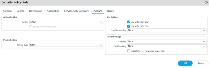
Note: The system-created rules don't log traffic by default, but you can override them for logging and profiles. Rules are evaluated sequentially, and unmatched traffic is dropped. Sessions are bidirectional, and the policy page is customizable.
5.1 Configure Security Policy
Navigate to the Policies section, then select Security. Click on the add icon to proceed.
To create a security policy, enter the source and destination zones and set the action to allow in the action tab.
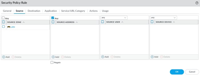
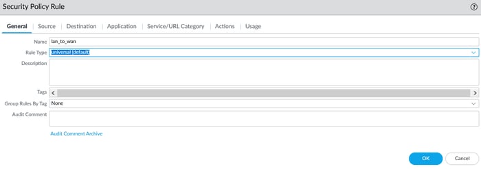
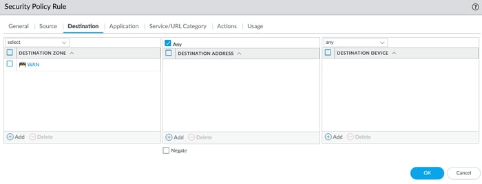
For example, you must create rules to access the DMZ from the LAN subnet. Additionally, you need to develop further rules to allow the DMZ to access the Internet or vice versa. To access a zone, you need to create a policy.
Step 6: Network Address Translation
Network Address Translation (NAT) is a process where a router or firewall translates private IP addresses into public IP addresses (or vice versa). This enables devices within a private network to access the Internet or outside devices to access internal servers. NAT enhances security by masking internal IP addresses and helps conserve the limited supply of IPv4 addresses.
6.1. Source NAT (SNAT)
Source Network Address Translation (SNAT) modifies the source address in the Internet Protocol (IP) header of outbound traffic on security gateway devices, such as Palo Alto firewalls. It conceals the actual IP address of devices behind the firewall.
SNAT is essential when an internal host connects to an external host or when a private host accesses a public host, changing the source host's private IP address to a public one.
Palo Alto Firewalls support three SNAT modes: Dynamic IP and Port, Dynamic IP, and Static IP, providing flexibility based on network needs and resources.
- Dynamic IP and Port:
Dynamic IP and Port are sources of NAT used in Palo Alto Networks firewalls. It translates multiple host source IP addresses to the same public IP address with unique source ports. This allows several clients to share a single public IP address efficiently, making it ideal when public IPs are scarce.
DIPP, interface-based NAT, or Network Address Port Translation (NAPT), relies on source ports for mapping. This enables a high oversubscription rate, as the same translated IP address and port can be reused. DIPP is commonly used when only one public IP is available. It conceals internal subnets behind a single external IP address, enhancing security and optimizing resources.
- Dynamic IP:
Dynamic IP NAT in Palo Alto Networks firewalls allows One-to-One (1:1) translations. Each private IP is mapped to a public IP from a predefined pool for the duration of the session. The NAT pool size limits the number of simultaneous translations, with private IPs dynamically assigned to the next available public IP.
If all public IPs in the pool are in use, new connections are dropped unless Advanced (Dynamic IP/Port Fallback) is enabled, which switches to port-based translation. Terminated sessions free up IPs in the pool for reallocation, ensuring efficient resource use.
- Static IP:
Static IP NAT in Palo Alto Networks firewalls allows for 1:1 static translation, which maps a single private IP address to a specific public IP address while keeping the source port unchanged. This type of NAT is typically used when an internal server needs to be accessible from the internet.
The size of the static NAT pool must match the number of source addresses being translated. Additionally, static NAT supports bidirectional translation, allowing for source IP translation for outbound traffic and destination IP translation for inbound connections. This ensures seamless accessibility for internal servers.
Go to the Policies tab, select NAT, and click the add icon to create source NAT.
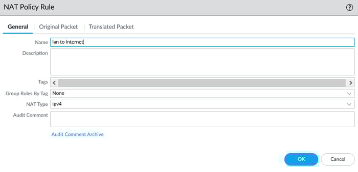
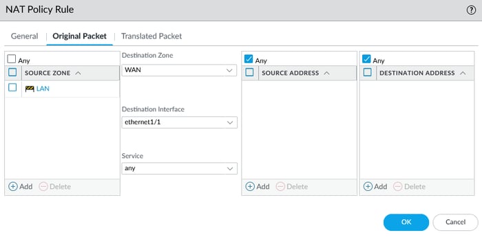
In the Original Packet tab, the source zone is LAN, while the destination zone is WAN. The destination interface refers to the interface connected to the outside.

6.2. Destination NAT
Destination Network Address Translation (DNAT) changes the destination address in the IP header of incoming packets and may modify the destination port in the TCP/UDP headers. DNAT redirects incoming packets with a public destination address to a private IP address.
DNAT is typically performed on packets entering the firewall, where the Palo Alto firewall translates a public destination address to a private address. It is a 1-to-1 static translation, with the option to perform port forwarding or port translation.
A typical example is users on the Internet accessing a web server hosted on your network or in your data center. In DNAT, a specific IP address is mapped to another particular IP address, enabling efficient inbound traffic management. in Palo Alto, you can configure DNAT in a two-way static IP or Dynamic IP (with session distribution)
- Static IP:
In Palo Alto Networks, firewalls map a public destination IP address and, optionally, a specific port to a private destination IP and port.
This supports bidirectional traffic flow, enabling both inbound and outbound connections with consistent IP and port configurations while allowing precise traffic control through direct one-to-one IP mapping or port forwarding.
- Dynamic IP (with session distribution)
In Palo Alto Networks, firewalls allow incoming traffic destined for a public IP to be dynamically distributed across a pool of private IP addresses. Each session is assigned to one of the available private IPs in the pool based on a round-robin or similar load distribution algorithm.
This ensures efficient utilization of internal resources and balanced traffic distribution, making it ideal for load balancing across multiple servers.
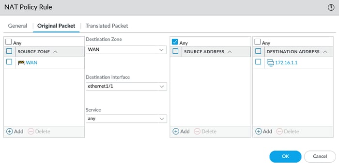
To configure DNAT, you should follow the same steps as you would for SNAT. However, there are crucial details to consider. Before we discuss them, take a look at the upper picture again.
In the illustration provided below, the source zone is WAN, and the destination zone is WAN. The destination interface refers to the interface connected to the router, also known as the gateway, and the destination address is the IP address of the WAN interface. Why is this the case?
In Destination NAT (DNAT), the source and destination zones are initially the same because the firewall processes packets in their pre-NAT state during the initial routing decision. Here’s why this happens:
- Pre-NAT Routing Decision:
When a packet arrives at the firewall, the routing decision is made based on its original destination IP and associated zone (pre-NAT). At this stage, the destination zone corresponds to the zone associated with the original (public) destination IP.
- NAT Policy Processing:
After the routing decision, the firewall applies the NAT policy, translating the public destination IP to a private IP. However, the destination zone remains tied to the original pre-NAT routing decision until the NAT translation is complete.
- Post-NAT Traffic Flow:
Once the packet is translated, the traffic flow is redirected to the private destination IP within the corresponding private zone. The source and destination zones may differ depending on the final NAT translation and security policy.
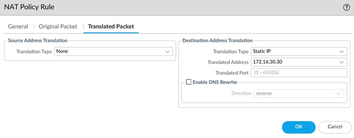
In the final step of DNAT, select the Translated Packet tab, select static IP as the translation type, set the server's IP address (Private IP address) as the translated address, and click. Remember to commit your configuration!
Summary
This article explored the essential steps for basic configuration, focusing on key settings such as network interfaces, security zones, and firewall policies. I plan to write additional articles in the future that cover advanced configuration in Palo Alto firewalls and best practices for further improving network security and performance.
![]()
![]()
![]()
![]()
![]()
![]()
![]()
FAQs
1. How to configure Palo Alto firewall step by step for beginners?
Follow this guide to set up management access, create security zones, configure interfaces, and set up NAT and security policies.
2. Why is NAT important in a Palo Alto firewall configuration?
NAT allows private IP addresses to communicate externally and protects internal addresses from direct exposure.
3. What are the core benefits of using a Palo Alto Next-Generation Firewall?
Application-based filtering (App-ID), user-based policies (User-ID), threat intelligence with WildFire, and URL Filtering capabilities for cybersecurity.
4. How do I troubleshoot connectivity issues?
Use CLI commands like show interface, ping, traceroute, and review logs under the Monitor tab.