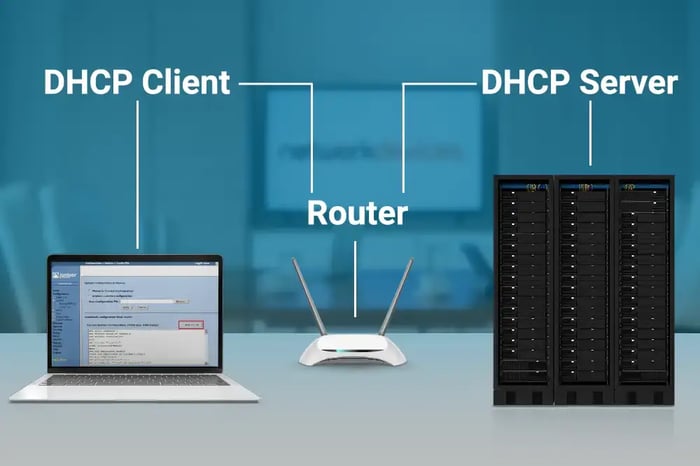

This in-depth article on troubleshooting DHCP relay over routing instances in Juniper networks provides a step-by-step guide to resolving everyday issues.
Dynamic Host Configuration Protocol (DHCP) is a widely used protocol for most networks as it provides a fast and automated way to provide IPs to multiple devices without causing assignment overlapping. It is supported by a vast majority of networking hardware enterprises, making it a vendor-compatible feature that follows RFC2131 standards.
Some topology designs that require a routing separation of DHCP traffic from other network traffic may have planning limitations due to the broadcast nature of the protocol. Nevertheless, Juniper Switch products include Layer 3 segmentation capabilities, which allow customers to isolate routing tables by creating multiple routing instances per device.

When Virtual Routing and Forwarding (VRF) feature is configured on a Juniper Switch, included interfaces and routing protocols will be independent of the main routing table and from other custom tables by splitting switches into multiple logical routing devices. This gives Network Administrators more control to troubleshoot and make routing changes without impacting other instances.
This article will cover a use case to split Client traffic from routing communications using Virtual Routing Instances with DHCP traffic as an example.
The Objective:
· New clients need to be added under VLAN 250.
· These clients must be isolated from the primary routing design per security requirements and future planning.
· The existing DHCP server must remain on the default instance to continue serving other VLANs.

STEPS:
Step 1: Configure the EX4300 as a pure Layer 2 Access Switch to interconnect the DHCP server with the QFX:
1. Configure the Server VLAN:
set VLANs DHCP_Server VLAN-id 10
2. Assign VLAN 10 to the interface pointing to the Server:
set interfaces ge-0/0/1 unit 0 family ethernet-switching interface-mode trunk
set interfaces ge-0/0/1 unit 0 family ethernet-switching VLAN members 10
3. Assign VLAN 10 to the interface pointing to the QFX:
set interfaces ae0 unit 0 family ethernet-switching interface-mode trunk
set interfaces ae0 unit 0 family ethernet-switching VLAN members 10
Step 2: Configure the QFX as the Core switch to act as a Layer 3 Gateway VLAN between the DHCP server and Client. IRBs (Integrated routing and bridging) must be enabled for this task to work.
1. Configure the Client VLAN and IRB:
set VLANs Client VLAN-id 250
set VLANs Client l3-interface irb.250
set interfaces irb unit 250 family inet address 10.220.252.1/24
2. Configure the Client’s interface as access to receive untagged traffic under VLAN 250:
set interfaces xe-0/0/1 unit 0 family ethernet-switching VLAN members 250
set interfaces xe-0/0/1 unit 0 family ethernet-switching interface-mode access
3. Configure the Server VLAN and IRB:
set VLANs DHCP_Server VLAN-id 10
set VLANs DHCP_Server l3-interface irb.10
set interfaces irb unit 10 family inet address 10.0.0.2/24
4. Configure the interface of the trunk port towards the EX4300:
set interfaces ae0 unit 0 family ethernet-switching interface-mode trunk
set interfaces ae0 unit 0 family ethernet-switching VLAN members 10
5. Isolate the Client VLAN to a custom VRF instance by assigning its IRB port:
set routing-instances MyInstance instance-type virtual-router
set routing-instances MyInstance interface irb.250
Step 3: Configure DHCP relay services on the QFX to forward DHCP requests from Clients on VLAN 250 to the DHCP server on the main instance:
1. Configure the DHCP relay under MyInstance VRF:
set routing-instances MyInstance forwarding-options DHCP-relay server-group DHCP 10.0.0.1 (IP of the DHCP server)
set routing-instances MyInstance forwarding-options DHCP-relay group DHCP active-server-group DHCP
set routing-instances MyInstance forwarding-options DHCP-relay group DHCP interface irb.250 (irb of the Client VLAN)
set routing-instances MyInstance forwarding-options DHCP-relay forward-only routing-instance default (default is the main routing instance’s name)
Note: Use the forward-only command to move the traffic between routing instances. When using forward-only, all overrides expect trust-option-82 option will be ignored. More info: https://www.juniper.net/documentation/en_US/junos/topics/reference/configuration-statement/forward-only-edit-forwarding-options-default-action.html
Step 4: Instruct switch to accept DHCP requests from MyInstance VRF to the main routing instance (called default) where the DHCP server resides:
1. Enable forward-only to accept DHCP request from other instances:
set forwarding-options DHCP-relay forward-only-replies
2. Include receive option to force packets to be sent to the Routing Engine for processing.
set routing-options static route 10.220.252.0/24 receive
CHECK RESULTS:
Once the Client requests a new IP, a DORA process will be triggered (Discover, Offer, Request, Ack) from Client to Server:
DHCP logs
· By monitoring the DHCP SERVER captures a DHCP Discover was found from Client MAC 2a:6a:fa:3a:18:33 sent by IRB.250:
|
Discover from IRB 250 on behalf of client 2a:6a:fa:3a:18:33
|
|
|
In IP 10.0.0.2.67 > 10.0.0.1.67: BOOTP/DHCP, Request from 2a:6a:fa:3a:18:33, length 326 Gateway-IP 10.220.252.1 Client-Ethernet-Address 2a:6a:fa:3a:18:33 DHCP-Message Option 53, length 1: Discover Circuit-ID SubOption 1, length 22: IRB-irb.250:xe-0/0/1.0 |
Discover in as a Request |
· The Server replies with a DHCP Offer:
|
Offer from server 10.0.0.1 offering available IP 10.220.252.9 to 2a:6a:fa:3a:18:33 |
|
|
Offer out as a Replay |
Out IP 10.0.0.1.67 > 10.220.252.1.67: BOOTP/DHCP, Reply Your-IP 10.220.252.9 Gateway-IP 10.220.252.1 Client-Ethernet-Address 2a:6a:fa:3a:18:33 DHCP-Message Option 53, length 1: Offer Lease-Time Option 51, length 4: 86400 Subnet-Mask Option 1, length 4: 255.255.255.0 Server-ID Option 54, length 4: 10.0.0.1 Circuit-ID SubOption 1, length 22: IRB-irb.250:xe-0/0/1.0
|
· The Client receives the Offer and responds with a Request:
|
Request from IRB.250 on behalf of the client to obtain the IP suggested by the server
|
|
|
In IP 10.0.0.2.67 > 10.0.0.1.67: BOOTP/DHCP, Request from 2a:6a:fa:3a:18:33 Gateway-IP 10.220.252.1 Client-Ethernet-Address 2a:6a:fa:3a:18:33 Server-ID Option 54, length 4: 10.0.0.1 Requested-IP Option 50, length 4: 10.220.252.9 DHCP-Message Option 53, length 1: Request Circuit-ID SubOption 1, length 22: IRB-irb.250:xe-0/0/1.0
|
Request in as a Request |
· The server acknowledges the Request and reserves the assigned IP on the pool:
|
Acknowledge to the Client confirming IP 10.220.252.9 was reserved.
|
|
|
ACK out as a Replay |
Out IP 10.0.0.1.67 > 10.220.252.1.67: BOOTP/DHCP, Reply Your-IP 10.220.252.9 Gateway-IP 10.220.252.1 Client-Ethernet-Address 2a:6a:fa:3a:18:33 DHCP-Message Option 53, length 1: ACK Lease-Time Option 51, length 4: 86400 Subnet-Mask Option 1, length 4: 255.255.255.0 Server-ID Option 54, length 4: 10.0.0.1 Circuit-ID SubOption 1, length 22: IRB-irb.250:xe-0/0/1.0
|
QFX outputs:
· We could correlate this information on the QFX with the below commands:
|
root@QFX_Coret> show DHCP relay statistics routing-instances MyInstance
|
|
|
Packets dropped: Total 0
Messages received: BOOTREQUEST 2 DHCPDECLINE 0 DHCPDISCOVER 1 DHCPINFORM 0 DHCPRELEASE 0 DHCPREQUEST 1
|
Messages sent: BOOTREPLY 2 DHCPOFFER 1 DHCPACK 1 DHCPNAK 0 DHCPFORCERENEW 0
Packets forwarded: Total 4 BOOTREQUEST 2 BOOTREPLY 2
|
root@QFX_Coret> ping 10.220.252.9 routing-instances MyInstance
PING 10.220.252.9 (10.220.252.9): 56 data bytes
!!!!!
--- device1.example.com ping statistics ---
5 packets transmitted, 5 packets received, 0% packet loss
round-trip min/avg/max/stddev = 0.956/0.974/1.025/0.026 ms
root@QFX_Coret> show arp no-resolve | match 10.220.252.9
MAC Address Address Interface Flags
2a:6a:fa:3a:18:33 10.220.252.9 irb.250 [xe-0/0/1.0] permanent remote
CONCLUSION
Juniper VRF is a practical feature for routing segmentation, and this example has converted a design case for DHCP. However, it could be implemented with other routing protocols or services such as BGP, OSPF, policies, firewall filters, etc. Hopefully, this guideline clarifies some of the benefits of this implementation and helps you in similar projects.