
Secure connectivity is essential for business operations in today's digital landscape. High availability (HA) ensures systems remain functional during failures using redundancy and failover mechanisms. Meanwhile, IPSec site-to-site VPNs encrypt communication between remote networks.
Sonicwall offers practical solutions integrating HA with IPSec VPNs, featuring advanced failover management and robust encryption. These tools are ideal for small and medium-sized enterprises (SMEs), providing reliable performance and affordable security for modern network requirements.
In this blog, we will discuss how to set up SonicWall HA and IPSec VPN step by step, understand the benefits of integrating these technologies, and troubleshoot common issues. Our goal is to provide a clear, easy-to-follow guide that will help you achieve a resilient and secure network infrastructure, even if you're a beginner.
Understanding SonicWall High Availability (HA) and IPSec VPN
In modern networks, high availability (HA) and IPSec site-to-site VPNs are essential for ensuring reliability and security.
High Availability (HA)
High Availability (HA) ensures that network systems remain operational during hardware or software failures. It minimizes downtime through redundancy and failover mechanisms, typically using either Active-Passive or Active-Active configurations. HA also supports scalability, maintaining reliability as the network grows.
IPSec Site-to-Site VPN
IPSec VPNs secure communication between remote networks by encrypting data and authenticating devices. They operate in two phases:
1. IKE Phase 1: Establishes a secure channel for negotiating encryption parameters.
2. IKE Phase 2: Encrypts and transmits data securely.
Combining SonicWall HA and IPSec VPN
Integrating SonicWall HA with IPSec VPNs provides continuous connectivity and secure data transmission.
- Continuous Connectivity: Ensures reliable failover capabilities to keep systems operational.
- Secure Data Transmission: Encrypts data during transfer to maintain security.
Step-by-Step Configuration for High Availability
Configuring High Availability (HA) ensures continuous network operation despite hardware or software failures. Below are instructions for setting up HA in Active-Passive mode with two devices.
Step 1: SonicWall HA Setup - Preparation Checklist
Before you start, ensure the following:
- Hardware Requirements: Use two identical devices with the same model and firmware version.
- Network Topology: Plan for a dedicated HA and monitored network interfaces.
- Licensing: Verify that HA functionality is included in your device license.
- IP Addressing: Assign unique management IP addresses to both devices for configuration access.
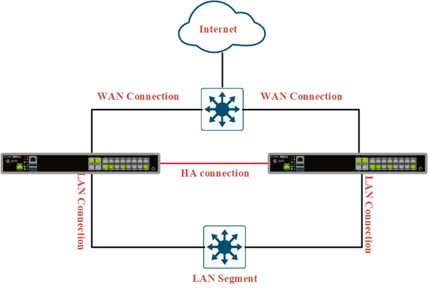
Step 2: Physical Connections
- Heartbeat Interface: Connect the dedicated HA interfaces on both devices using a direct Ethernet cable.
- Network Interfaces: Connect devices to upstream and downstream network segments (e.g., routers, switches).
Step 3: Initial Setup on Primary Device
1. Access the Device: Log in to the primary device’s management interface using its IP address.
2. Enable HA Mode: Click on the Device icon at the top of the menu, select High Availability from the left-hand menu, and choose Settings.
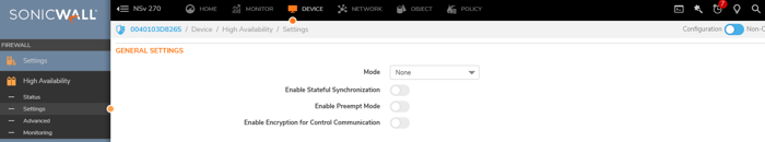
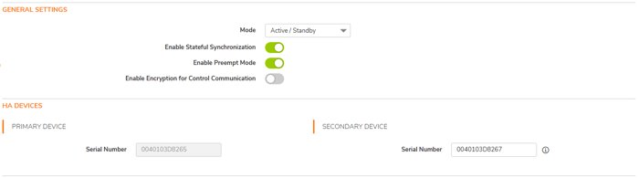
3. Select HA Mode: Select the Active-Passive option for failover-based redundancy in the General Settings.

4. Enable Stateful Synchronization: Stateful Synchronization ensures seamless failover by continuously syncing network connections and VPN tunnel data between the primary and secondary units, allowing the secondary to take over without disrupting active connections.
5. Enable Preempt Mode: Allow the primary SonicWall to resume control once it becomes available. If disabled, the backup remains active. Disabling Preempt Mode when using Stateful High Availability is recommended, as it may trigger unnecessary failovers.
6. Enable Encryption for Control Communication: To encrypt HA control communication between the active and standby firewalls, select Enable Encryption for Control Communication. This option is not selected by default. If you connect two HA ports directly, you do not need to enable this feature.
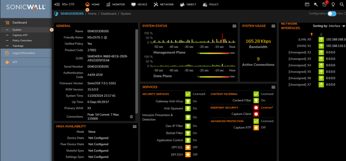
7. HA Devices: In this section, You Should provide the serial number of the second device. The serial number can be found in the Home Menu under the general section.
8. HA Control Interface: Select the interface for the HA Control Interface. This option is grayed out, and the interface will be displayed if the firewall detects that it has already been configured.

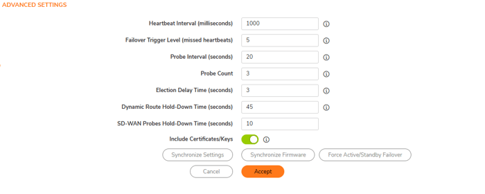
9. Advanced Setting: The Advanced page also allows you to fine-tune several High-Availability options, which manage the settings that trigger the High-Availability pair to failover from the primary to the backup appliance. SonicWall recommends that these values remain unchanged. You can manually sync settings or update firmware to modify the active and standby rules.
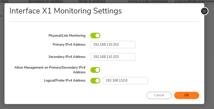
10. Monitoring: The Monitoring page allows you to configure physical and logical interface monitoring. Enabling physical interface Monitoring enables link detection for the designated HA interfaces. The link is detected at the physical layer to assess its viability.
Logical monitoring involves configuring the SonicWall to monitor a reliable device on one or more connected networks. Failure to periodically communicate with the device by the Active unit in the HA Pair will trigger a Failover to the Idle unit. No action will be taken if neither unit in the HA Pair can connect to the device.
In this example, I use the X1 interface from both firewalls for monitoring. You can choose multiple interfaces for monitoring; for example, you can select the WAN interface.
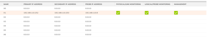
Note: If you select the X1 interface for monitoring, enter the same IP address and subnet as the X1 interface. Why?
The answer is straightforward. SonicWall communicates with other devices or addresses through X1; the target IP must belong to the same subnet unless a specific route is defined.
Why doesn't SonicWall use the IP address assigned to the selected interface for monitoring?
- The interface's primary IP is already used for routing, device operations, and regular traffic. A separate IP ensures a dedicated address for monitoring or management, avoiding conflicts with regular interface traffic.
- In an HA environment, primary and secondary devices need unique IPs for management and monitoring. For example, Primary Device: 192.168.110.252, Secondary Device: 192.168.110.253. These allow independent monitoring of each device even when one is active and the other is on standby.
- Without a unique IP, accessing and managing the standby device would be impossible, as the shared interface IP would only be active on the primary device.
Step4: Checking The Status of HA
The Status section in a SonicWall device's High Availability (HA) configuration provides real-time information about the HA setup's current state. This information is critical for monitoring and troubleshooting the health and performance of the HA environment.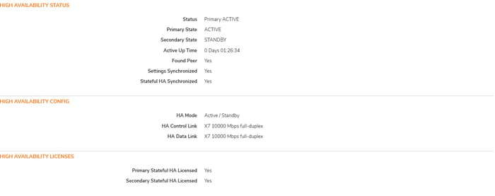
Step-by-Step Configuration for IPSec Tunnel Interface Configuration
This section provides instructions for configuring the IPSec tunnel on a SonicWall firewall. To illustrate this process, we will focus on configuring one of the firewalls. However, this guide can also be used to configure the other firewalls as needed.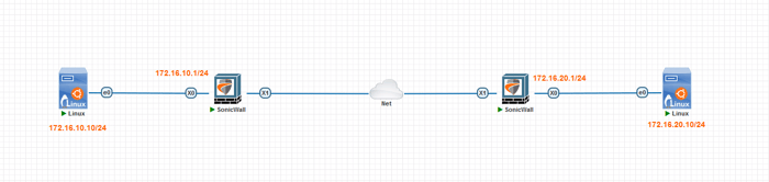
Step1: Create the IPsec Tunnel Interface
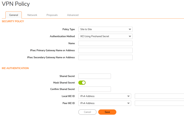
- Policy Type: Select the Tunnel Interface. Once selected, the VPN policy page will appear as shown.
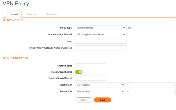
- Authentication Method: Select IKE (Internet Key Exchange) using a pre-shared secret.
- IPsec Primary Gateway Name or Address: Enter the IP address of the remote SonicWall firewall. The two firewalls must be able to communicate over the Internet.
- Shared Secret: Enter the shared secret or essential. This value must match on both SonicWall firewalls.
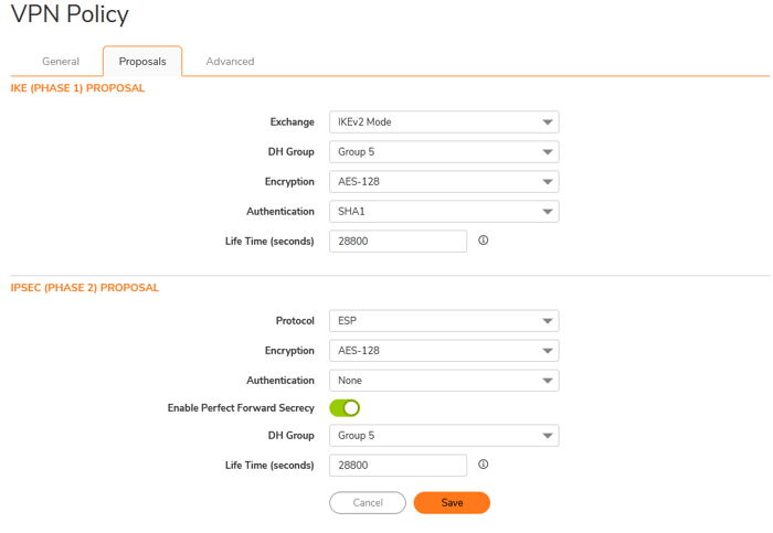
In the proposal tab, enter the values for Phase 1 and Phase 2. These parameters must match on both sides.
In the Advanced table, select the parameters recommended by Sonicwall.
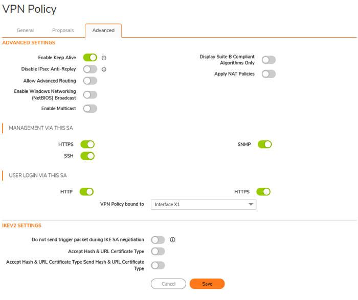
- Enabling Keep Alive: This feature in IPsec VPN configurations ensures that the VPN tunnel remains active and does not drop due to inactivity. When this feature is enabled, the VPN device sends periodic messages across the tunnel, typically pings or keep-alive packets. This process keeps the tunnel open even if no user traffic is transmitted.
- Allow Advanced Routing: This option supports dynamic protocols and advanced routing features, including OSPF, RIP, BGP, and policy-based routing (PBR).
- It is especially beneficial for complex network environments that require dynamic route management or the management of multiple VPN tunnels with advanced traffic control. Enable this feature if you need to use dynamic routing protocols.
- Enable Windows Networking (NetBIOS) Broadcast: This option enables NetBIOS traffic to pass through the VPN tunnel, allowing Windows devices on different networks to communicate as if they were on the same LAN.
- Management via this SA: Administrators can manage the SonicWall device through a specific Security Association (SA) within a VPN tunnel. This capability allows access to SonicWall’s web management interface and other management services, such as SSH, via the VPN connection.
- This feature is handy for remote management, ensuring administrators can securely configure or monitor the device over the IPsec tunnel. However, it is essential to restrict this access to trusted sources and safeguard it with strong authentication measures to prevent unauthorized access.
- User Login via this SA: Users can authenticate and log in to the SonicWall device for access control or monitoring through a specific Security Association (SA) within a VPN tunnel.
- This method is commonly used when remote users need secure access to network resources. Users can log in via the VPN connection using their credentials when enabled.
- This option is usually paired with role-based access control to ensure that only authorized users can access specific features or resources. Robust authentication methods, such as multi-factor authentication (MFA), must be used to enhance security.
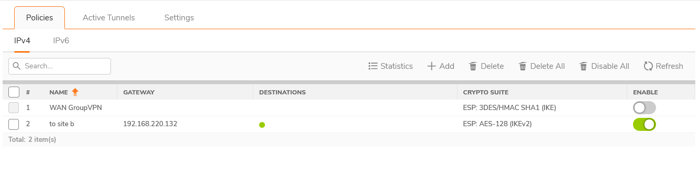
Make sure to repeat the same steps on the other side. If done correctly, your tunnel will be established, and you will notice a green light in the destination field next to the name of your tunnel, as shown in the picture below.
Step2: Configure The VPN Tunnel Interface
Configuring an interface in SonicWall's Tunnel Interface mode creates a versatile, route-based VPN that enhances traffic routing and policy enforcement control. Unlike traditional policy-based VPNs, which rely on static policies to define allowed traffic, a tunnel interface establishes a logical interface that can be utilized with dynamic routing, advanced traffic rules, and network segmentation.
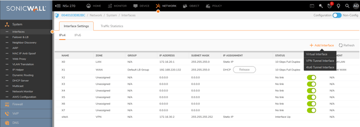
- Navigate to Network > System > Interfaces > add Interface> VPN Tunnel Interface. When you click on the VPN Tunnel Interface, a new window will open.
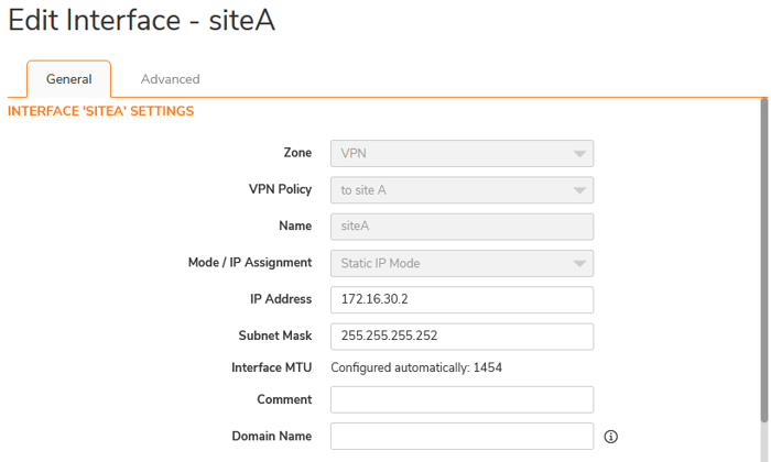
- Zone: The setting should be configured to use a VPN.
- VPN Policy: The name of the VPN was set up in the previous step.
- IP Address: Assign a /30 IP address to the tunnel interface, which will be used for routing between two sites.
Make sure to follow the same steps on the opposite side.
Step 3: Configure Routing
This step configures a static route to direct traffic between the local and remote networks through the VPN tunnel interface. This configuration ensures proper data flow across the tunnel for connected subnets.
- Navigate to Policy > Rules and Policies > Route Policy and then click on ADD
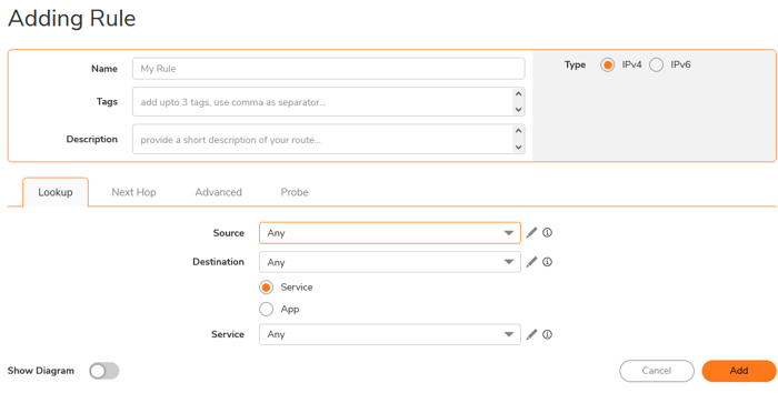
- Source: Click the pen icon, then select the Add New Address option. Enter the name and local IP address, and set the zone assignment to LAN.
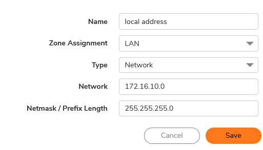
- Destination: Click the Pen Icon and select the Add New Address option. Enter the Name and remote IP address, and set the Zone Assignment to VPN.

- Services: set to any.
In The Next Hop, select Standard Route, select the Interface created in Step 2, and set Metric to 10. 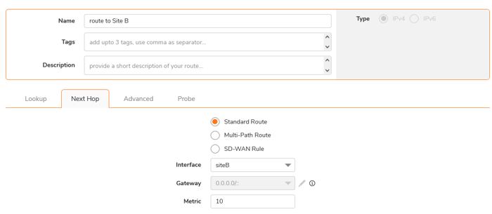
Make sure to follow the same steps on the opposite side.
Step 4: Configure Access Rules
These rules control the traffic between the VPN tunnel and local and remote networks. They specify the permitted traffic based on the source, destination, and services.
We must create two rules in each firewall: one for incoming traffic and one for outgoing traffic.
To set up your security policies, navigate to Policy > Rules and Policies > Security Policy and click ADD. This configuration is relatively straightforward. Make sure to select the appropriate source and destination IP addresses and the relevant interfaces. You must create one policy for traffic from LAN to VPN and another for traffic from VPN to LAN.
- LAN to VPN Access Rule

- VPN to LAN Access Rule

Make sure to follow the same steps on the opposite side.
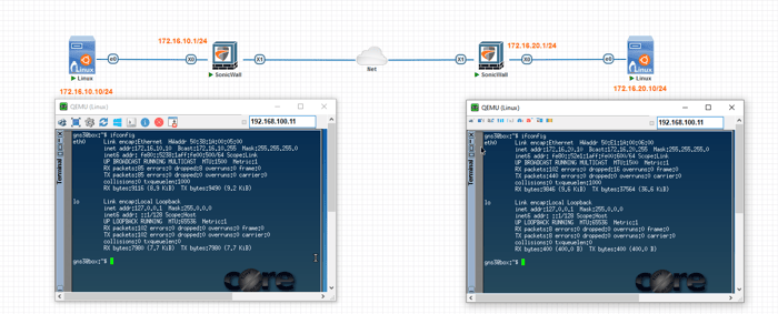
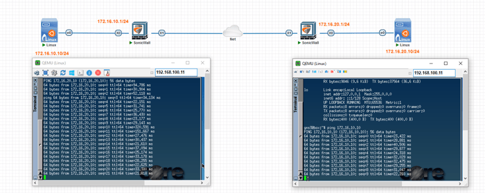
Step 5: Ping Tests
You can ping each host on a remote site following all the steps.
Conclusion
In conclusion, High Availability (HA) and IPSec VPN are essential for creating resilient and secure distributed networks. SonicWall HA provides redundancy, ensuring uninterrupted access to resources, while IPSec VPN ensures encrypted communication between remote locations.
This combination guarantees reliable, secure connections—a necessity for businesses with critical operations, remote workforces, or geographically dispersed locations.
By following this step-by-step guide, small and medium-sized enterprises (SMEs) can establish a robust, fail-safe network infrastructure that adapts to growing demands while safeguarding sensitive data. Whether it's securing remote access, preventing network downtime, or optimizing performance, SonicWall's HA and IPSec VPN solutions are here to keep your network running smoothly.
Browse our selection of SonicWALL firewalls to find the perfect solution for your business.