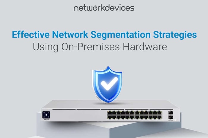

Network segmentation is now crucial in cybersecurity, helping contain threats and prevent lateral movement during breaches. Many IT managers acknowledge its importance but are unsure how to implement it. Managed switches are vital, justifying their higher cost. If network segmentation seems complex, this guide will help you make it manageable and effective with existing or prospective switches. It explains a simple, scalable VLAN-based strategy that enhances security and supports smarter switching investments.
The Security Value of Managed Switches
So, why are managed switches essential for segmentation? Because they provide the control plane you need to create, configure, and enforce VLANs. Here's what managed switches offer that unmanaged switches don’t:
Feature | Managed Switch | Unmanaged Switch |
VLAN Configuration | Yes | No |
Port Security | Yes | No |
802.1Q Trunking | Yes | No |
QoS & Traffic Prioritization | Yes | No |
Remote Management | Yes | No |
Without managed switches, you cannot implement true segmentation.
What is Network Segmentation
Network segmentation splits a network into isolated parts to prevent malware spread, protect sensitive data, and enhance traffic control. In a flat network where all devices share the same domain, a single compromised device can be dangerous. Segmenting into VLANs creates virtual switches, isolating groups for added security.
Why VLANs Exist
VLANs solve two major problems:
- Broadcast Containment: Reduces unnecessary network traffic
- Security Isolation: Prevents one compromised device from accessing others
What occurs when a VLAN is created?
Creating a VLAN on a managed switch involves more than just labeling; it effectively creates a virtual switch within your physical device. Here’s a look at what occurs behind the scenes:
- Logical Separation: Each VLAN acts like a separate Layer 2 broadcast domain. Devices in different VLANs don’t share ARP broadcasts, DHCP traffic, or MAC learning tables.
- Tagged or Untagged Traffic: VLAN-aware ports can tag traffic with a VLAN ID using the IEEE 802.1Q standard. This tells the switch to which virtual network the traffic belongs.
- Port Configuration:
- Access ports carry untagged traffic for a single VLAN.
- Trunk ports carry multiple VLANs between switches or to routers.
- Device Isolation: Even if devices are plugged into adjacent ports and on different VLANs, they cannot communicate directly.
VLANs vs. Subnetting: What’s the Difference?
Many IT pros confuse VLANs with IP subnets, and while they often work together, they operate on different layers of the network:
Feature | VLAN | Subnet |
OSI Layer | Layer 2 (Data Link) | Layer 3 (Network) |
Purpose | Logical segmentation within switches | IP addressing & routing logic |
Separation Method | MAC address & VLAN ID | IP address and subnet mask |
Needs Routing? | Yes, to talk between VLANs | Yes, to talk between subnets |
How They Work Together
You typically assign one subnet per VLAN:
- VLAN 10 → 192.168.10.0/24
- VLAN 20 → 192.168.20.0/24
- VLAN 30 → 192.168.30.0/24
The VLAN separates traffic on the switch, while the subnet tells routers and firewalls how to handle traffic between VLANs.
Why This Matters for Security?
Combining VLANs with subnets allows for the implementation of network-layer security policies, including firewall rules, access controls, and DHCP scope separation.
Inter-VLAN Routing
By design, devices in different VLANs are isolated, enhancing security. However, there are cases when specific traffic needs to pass between VLANs. This is where inter-VLAN routing becomes useful.
What Is Inter-VLAN Routing?
Inter-VLAN routing is the process of routing traffic between different VLANs, using:
- Router-on-a-Stick: A single router interface set up with multiple sub-interfaces, each assigned a VLAN ID.
- Layer 3 Switch: A managed switch capable of Layer 3 routing, typically with built-in VLAN awareness.
Why You Might Need It
Allow staff computers (VLAN 10) to access a printer (VLAN 20).
- Allow IoT devices (VLAN 30) to send data to a cloud gateway.
- Permit admin access from a secure VLAN to all other VLANs.
Security Tip
Firewall rules should tightly control Inter-VLAN routing:
- Only allow specific ports, protocols, and directions.
- Use ACLs on Layer 3 switches or firewall policies to enforce restrictions.
Real-World Use Case: Small Office Network
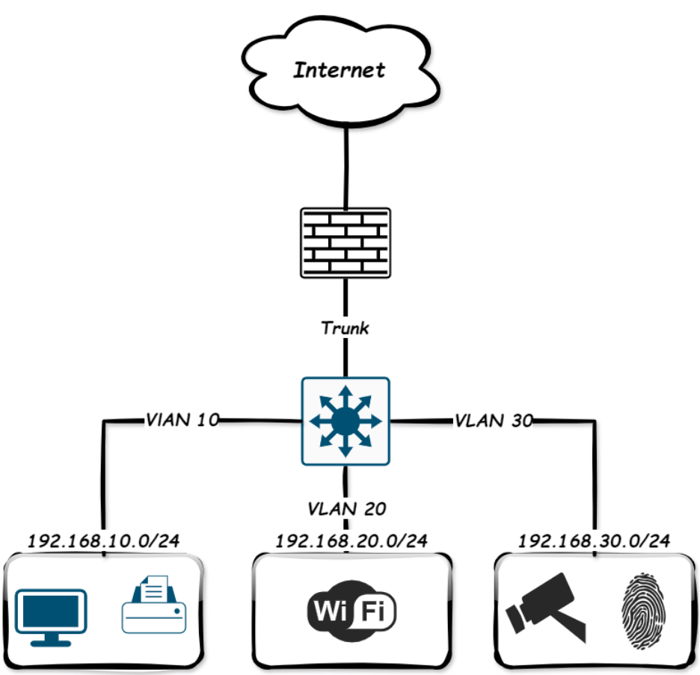
Let’s take a simple example of a small office network. You want to isolate:
- Staff computers and file servers (Corporate VLAN).
- Visitor smartphones and laptops (Guest VLAN).
- Smart TVs, cameras (IoT VLAN).
Below is a basic network diagram of how that looks with VLANs configured on managed switches.
Setting Up VLANs with Managed Switches
Let’s walk through how to configure this using typical managed switches. In the top diagram, each VLAN is assigned a distinct IP subnet; at this point, we have created the VLAN on the switch.
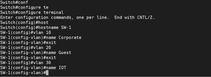
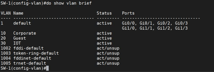
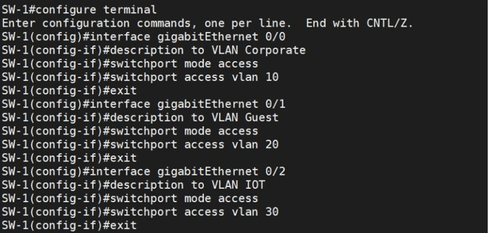
As you can see, three VLANs were created, and now we should assign each switch’s port to a specific connection VLAN.
Now, check the status of VLANs.
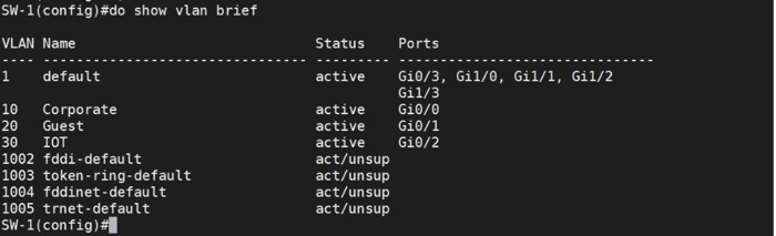
We have now created the VLANs. In the next stage, we will set up the Switch Virtual Interface (SVI).
SVI: The Key to Layer 3 Switching
A Switch Virtual Interface (SVI) is a logical Layer 3 interface on a switch, tied to a specific VLAN. It allows the switch to route traffic between VLANs without relying on an external router.
How an SVI Works
An SVI acts as the virtual gateway for devices in a VLAN, enabling communication beyond their network. The switch can route traffic between VLANs directly by assigning an IP address to the SVI.
- An SVI is created for a VLAN (e.g., VLAN 10) and assigned an IP address.
- Devices in that VLAN use the SVI IP as their default gateway.
- If another VLAN also has an SVI, the switch can route between them. This is inter-VLAN routing done internally.
Why Use an SVI Instead of Router-on-a-Stick?
- Higher performance (hardware-based routing in the switch ASIC).
- Simplified design.
- Easy scalability; add a new VLAN and SVI.
How to Create SVI
Setting up an SVI is straightforward; assign an IP address to a VLAN Interface on your managed switch. This IP acts as the VLAN’s gateway, enabling devices within the VLAN to access other networks via the switch.
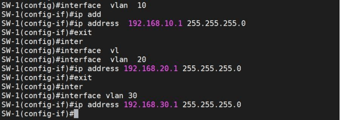
When you run the show ip route command, the switch should display a routing table listing all connected VLAN networks and their gateways. Let's run the command.
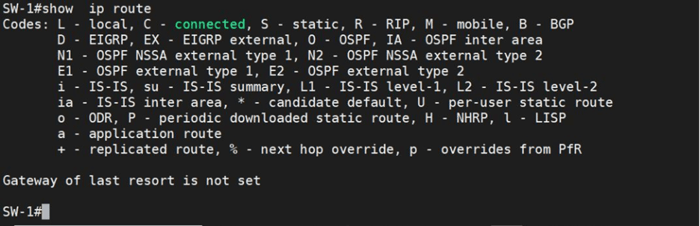
Surprisingly, the switch does not automatically add routes to the routing table. This is because it still operates at Layer 2. To switch to Layer 3 mode and populate the routing table with VLAN networks, you must run the ip routing command and check the routing table again.
As you can see, nothing has happened again. Why? Let's do some troubleshooting with the bot.

As shown, three VLAN interfaces have been shut down automatically. After entering the no shut command on each SVI, the switch has now populated the routing table with data from the SVIs. Now, clients in different VLANs can communicate with each other, provided their gateways are correctly configured for their respective VLANs.
Router-on-a-Stick
Router-on-a-Stick is a network configuration that allows communication between clients on different VLANs through a single physical interface on a router.
- The router interface is configured as a trunk port that carries traffic for multiple VLANs.
- Each VLAN is assigned a subinterface on the router, with its IP address acting as the default gateway for that VLAN.
- When clients in different VLANs want to communicate, their traffic is sent to their VLAN’s default gateway on the router.
- The router routes traffic between these VLANs through the trunk link, allowing inter-VLAN communication.
How It Works
- The switch segments the network into VLANs, separating clients logically.
- A trunk link connects the switch to the router, carrying traffic for all VLANs with VLAN tags.
- On the router, the single physical interface is divided into multiple subinterfaces, each configured with an IP address for a specific VLAN.
- When a client transmits a packet to a device in a different VLAN, the packet is routed to the subinterface IP address (default gateway) of the router for that VLAN.
- The router receives the VLAN-tagged packet, removes the tag, processes routing between VLANs, then adds the appropriate VLAN tag before sending it back to the switch.
- The switch forwards the packet to the destination client in the target VLAN.
- This process enables inter-VLAN communication using only one physical router interface.
Question:
Can I add a firewall instead of a router to a router-on-a-stick setup?
NGFW firewalls combine routing and security features, allowing them to perform inter-VLAN routing and filtering simultaneously.
How to configure Router-on-a-Stick?
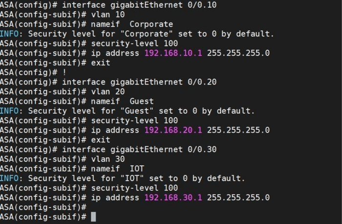
Assuming the switch we configured has three VLANs and connects to a Cisco ASA firewall, the first step is configuring the interface connected to the ASA as a trunk port.
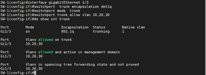
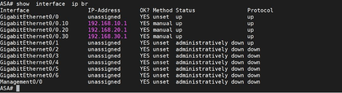
Next, configure the ASA port connected to the Switch. Cisco ASA firewalls do not support SVIs (Switched Virtual Interfaces) like a Layer 3 switch or router. Instead, you configure subinterfaces on a physical interface to manage multiple VLANs, similar to SVIs, but specific to ASA.
Summary
The guide explains network segmentation with on-premises hardware, focusing on managed switches, VLANs, and routing to improve cybersecurity through traffic isolation, threat containment, and preventing lateral movement. Using examples like a small office network, it shows how VLANs, subnets, and inter-VLAN routing enhance security and traffic control. It combines concepts with step-by-step config, making it useful for IT managers aiming for scalable, secure networks.